Virtual Memory
CS 345 - Project Four
Purpose
Memory management involves a complex interrelationship between computer hardware and operating system software. In a virtual memory system, memory references within a task are logical addresses that are dynamically translated into physical addresses during run time. As such, a task may move in and out of main memory and occupy different regions of physical main memory at different times during the course of its execution. In addition, a task may be broken into a number of pieces (pages) that may or may not be contiguous in main memory (frames). Thus, not all pages of a task have to be physically present nor contiguous in main memory during execution. This is the basis for virtual memory.
Project 4 is designed to help the student understand:
- the concepts of swap space, main memory, and virtual memory.
- the details of page faulting and a page replacement algorithms.
- what memory access, hit, and fault counts are and how to track them.
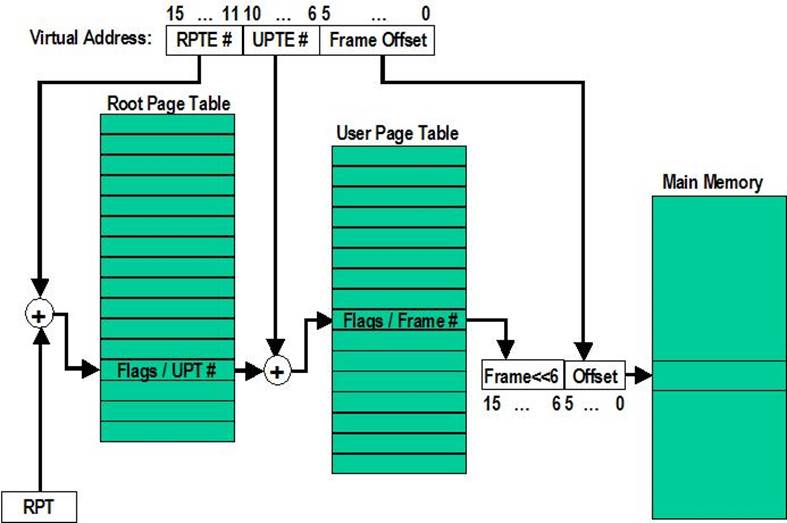
- how to implement virtual address translation with a two-level page table.
- the additional overhead of a virtual memory system.
- how virtual memory functions are divided between operating system software and the hardware memory management unit (MMU).
LC-3 Processor
The LC-3 (Little Computer 3) is an ISA definition for a 16-bit computer. Its architecture includes physical memory mapped I/O via a keyboard and display; TRAPs to the operating system for handling service calls; conditional branches on N, Z, and P condition codes; a subroutine call/return mechanism; a minimal set of operation instructions (ADD, AND, and NOT); and various addressing modes for loads and stores (direct, indirect, Base+offset, PC-relative, and an immediate mode for loading effective addresses). Programs written in LC-3 assembler execute out of a 65536 word memory space. All references to memory, from loading instructions to loading and storing register values, pass through the getMemAdr() function. The hardware/software function of Project 4 is to translate virtual addresses to physical addresses in a restricted memory space. The following is the default, pass-through, MMU code for all memory references by the LC-3 simulator.
unsigned short int
*getMemAdr(int va, int rwFlg)
{
unsigned short int pa;
// turn off virtual addressing for system RAM
if (va < 0x3000) return &memory[va];
// translate virtual address to a physical address
pa = va;
//
return physical pointer to accessed memory location
return &memory[pa];
} // end getMemAdr
Project Requirements
The following are important guidelines for programming the Virtual Memory assignment:
1) Main Memory: The maximum physical memory size of the LC-3 is 65536 words (216+1 = 128K bytes). For this assignment, you will need to allow the user to specify the physical size of main memory, ranging from 194 to 1024 frames (24.25K to 128K bytes). A page/frame size is equal to 26 words (128 bytes).
2) Virtual Memory: The full 16-bit virtual address space needs to resolve to the physical address space of the LC-3 using a two-level page table implementation (see Stallings, Chapter 8.1). Up to 32 tasks may simultaneously access LC-3 physical memory via their task Root Page Table pointer. All MMU data including frame allocation tables, Root Page Tables, and User Page Tables are to be stored in LC-3 memory. Use the advanced clock algorithm for page replacement (Stallings pp. 368-373).
3) Swap Space: Each page in swap space is 26 words (128 bytes). We will simulate 4096 pages (212 ´ 27 = 219 = 524,288 bytes) of swap space. Since virtual addresses in the LC-3 simulator are 16 bits long, each task could address up to 64K words of its own memory, regardless of the physical size of memory. Frames unloaded from physical memory must be stored in one of the 4096 pages of swap space. For Project 4, this swap space is a random-accessed memory array used to simulate a hard disk. The unit of access to swap space is one page.
4) Page Replacement: Once all of the available physical frames in main memory have been acquired, replace older frames with newly referenced pages according to the simple clock algorithm. Pinned frames are never replaced. Dirty frames are written back to swap space before being allocated to another task. The root page table (RPT) for each task is always implicitly pinned in memory. Additionally, a user page table (UPT) page is pinned in memory while it contains any valid page table entries (indexes to pages in physical memory).
5) A page table entry (RPTE and UPTE) is four bytes. Please format them as follows:
- Frame valid (1 bit): one if referenced frame is in main memory; zero otherwise.
- Dirty (1 bit): one if referenced frame has been altered; zero otherwise.
- Reference (1 bit): one if frame has been referenced; zero otherwise.
- Pinned (1 bit): one if frame is pinned in memory; zero otherwise.
- Frame number (10 bits): If referenced page is in memory, this value specifies which frame it occupies. (1024 frames ´ 64 words = 210 ´ 26 = 216 bytes = 65536 words.)
- Swap valid (1 bit): one if referenced page has been allocated in swap space; zero otherwise.
- Swap page number (12 bits). This specifies where referenced page is stored in swap space. When you load a page into memory, you should include this value in your frame table summary. (4096 pages ´ 128 bytes = 212 ´ 27 = 219 bytes = 524,288 bytes.)
|
|
|
|
|
|
|
frame
# (0-1023) |
|
|
|
|
page
# (0-4095) |
||||||||||||||||||||
|
F |
D |
R |
P |
- |
- |
f |
f |
f |
f |
f |
f |
f |
f |
f |
f |
S |
- |
- |
- |
p |
p |
p |
p |
p |
p |
p |
p |
p |
p |
p |
p |
6) Your MMU should be able to support up to 32 tasks, each with its own virtual address space. (Note: this may be limited by the size of the virtual swap space.) The root page tables are static and pinned. The associated user page tables and frames are allocated from the available physical memory. The user should be able to view the contents of any page in swap space or main memory. The user should also be able to see a summary of the contents of all physical frames in memory.
7) Computing Performance Statistics: Because of the virtual address translation mechanisms, each memory request actually requires a minimum of three memory accesses: one to the RPT, one to the UPT, and one to the actual page. If any page is not in memory, a page fault occurs (miss). Hit and fault counts should be updated for each LC-3 instruction. The fault rate is the fraction of memory accesses that result in a fault, ie. Fault rate = memPageFaults / (memPageFaults + memHits). The sum of the hits (memHits ranges from 1-3) and the faults (memPageFaults ranges from 0-2) should always equal the number of memory accesses (memAccess) for each instruction.
8) User Interface: You are free to create your own CLI commands to display running results of your memory management unit (MMU). Most of the following functionality is provided, but you are still required to verify their validity.
- A way for viewing pages in swap space.
- A way for viewing frames in main memory, both physically and virtually.
- A way for displaying performance statistics (requests, hits, misses).
- A way to display a RPT, UPT, and frame contents as they pertain to the virtual/physical organization of main memory.
Implementation Strategy
- Read and comprehend Stallings Chapter 8, especially Sections 1 and 2.
- Comprehend these lab specs. Discuss questions with classmates, the TA’s and/or the professor. Make sure you understand what the requirements are! It's a tragedy to code for 20 hours and then realize you're doing everything wrong.
- Validate that the demo LC-3 simulator works for a single task with pass-through addressing (virtual equals physical) by executing the commands “crawler” and “memtest”.
- Design your MMU. Break the problem down into manageable parts. (See step 7 below.)
- Comprehend structures for PTEs, frame allocation, and Swap Page allocation. Decide how you want to extract the values for the various fields in PTEs and VM addresses.
- Use either the paging routines provided or code your own function to handle the swap space.
- Incrementally add support for the actual translation of virtual addresses to physical addresses with page fault detection as follows:
- Implement page fault frame replacement using available memory frames only. This should allow you to execute a test program in a full address space.
- Implement clock page replacement algorithm to unload data frames to swap pages (write-thru paging) and reload with a new frame or an existing frame from swap space. This should allow you to execute all the test programs in a 32k word address space (20k of paging frames).
- Implement clock page replacement of User Page Tables when there are no physical data frame references in the UPT. This will be necessary when running in a small physical space (1k words) with multiple tasks.
- Set a frame’s dirty bit when a frame is created, altered, or the rwflg is non-zero. Use the dirty bit to determine if a frame needs to be written back to swap space.
- Use the vma function to access a single virtual memory location and then display any non-zero RPT and UPT entries. Implement various levels of debug trace to watch what is going on in your MMU. You may use the provided display functions where feasible.
- Successful completion of this project requires exactness. Although there are many ways to implement frame management, there is little (if any) room for error!
Implementation
1. Do the following:
· Verify a clean compilation of your LC-3 virtual memory simulator. Validate that “crawler” and “memtest” programs execute properly.
· Modify the getMemAdr() function (OS345mmu.c) to handle virtual memory addressing.
· Implement a simple clock page replacement algorithm with a reference bit to unload LRU frames.
· Use the provided 0.5MB page swap table routine to simulate paged disk storage (4096 pages) or implement your own routine.
· Modify your im command to do the following:
1. Adjust the upper physical memory limit of the LC-3 memory.
2. Initialize (clear) LC-3 memory (which initializes all RPT and UPT entries).
3. Clear the hit/miss counts and reset your clock replacement routine.
4. Recovery all physical frames and swap pages.
· Use the following CLI commands to verify and validate your virtual memory system. (Most of these routines are provided, but may require some adaptation to your system.)
o dfm <#> Display LC3 memory frame <#>
o dft
Display frame allocation table
o dm <sa>,<ea> Display physical LC3 memory from <sa>
to <ea>
o dp <#> Display page <#> in swap space
o dv <sa>,<ea> Display virtual LC3 memory <sa> to
<ea>
o im <ea> Init LC3/Set upper LC3 memory limit
o rpt <#> Display task <#> root page table
o upt <p><#> Display task <p> user page table <#>
o vma <a> Access <a> and display RPTE’s and
UPTE’s
o vms Display LC3 statistics
2. Demonstrate that LC-3 tasks run correctly. Be able to dynamically change LC-3 memory size (im command) and chart resulting changes in page hits/faults and swap page accesses as shown below. Memory accesses, hits and faults are defined as follows:
Hit (memHits) = access to task RPT, UPT, or data frame. (Exclude accesses below 0x3000.)
Fault (memPageFaults) = access to a task page that is undefined or not currently in a memory frame.
Memory access (memAccess) = sum of memory hits (memHits) and memory faults (memPageFaults).
|
|
Crawler |
Memtest |
||||
|
Frames: |
320 |
16 |
2 |
320 |
16 |
2 |
|
Accesses: |
|
|
|
|
|
|
|
Hits: |
|
|
|
|
|
|
|
Faults: |
|
|
|
|
|
|
|
Page
Reads: |
|
|
|
|
|
|
|
Page
Writes: |
|
|
|
|
|
|
|
Swap
Pages: |
|
|
|
|
|
|
Grading and Pass-off
Your Virtual Memory assignment is to be demonstrated in person to a TA. The assignment is worth 10 points, which will be awarded as follows:
·
4 points – Successfully execute crawler and memtest in 20k words (x3000 – x7FFF, 320 frames).
·
3 points – Successfully execute crawler and memtest in 1k words (x3000 – x33FF, 16 frames).
·
1 point – Successfully execute 5 or more
LC-3 tasks simultaneously in 16 frames of LC-3 memory.
·
1 point – Correctly use the dirty bit to
write only altered or new memory frames to swap space.
·
1 point – Chart and submit the resulting memory access, hit, fault, and swap
space statistics (displayed by the vms
command) after executing crawler (and then memtest) in 320 and 16 frames (and 2 frames). (Be sure to execute im before
each test.) The statistics must be
submitted before any grade will be recorded.
·
-1 point penalty for each school day
late.
In addition, after completing the above requirements, the following bonus points may be awarded:
· +1 point bonus for early pass-off (at least one day before due date.)
· +1 point bonus for adding a task frame/swap page recovery mechanism of a terminated task.
· +1 point bonus for implementing the advanced clock algorithm and charting the results.
· +1 point bonus for joining the 2-frame club. (Successfully execute 5 or more LC-3 tasks simultaneously in 2 frames of LC-3 memory. Chart the memory accesses, hits, and faults.)
NOTE: Bonus points may be received anytime before the due date of the next project (regardless of any late penalties) as long as the project requirements have been completed.
Sample Output
CS345 F2011
New Task[0] myShell
0>>p4 2
Validate arguments...
Setting upper memory limit to 0x3080
Physical Address Space = 2 frames (0.3kb)
New Task[1] memtest
Load "memtest.hex" from system
Memory loaded!
PC=0x3000
New Task[2] crawler
Load "crawler.hex" from system
Memory loaded!
PC=0x3000
Crawler R1.1
MemTest R1.0a
New Task[3] memtest
Load "memtest.hex" from system
Memory loaded!
PC=0x3000
New Task[4] crawler
Load "crawler.hex" from system
Memory loaded!
PC=0x3000
Crawler R1.1
MemTest R1.0a
New Task[5] memtest
Load "memtest.hex" from system
Memory loaded!
PC=0x3000
23>>
New Task[6] crawler
Load "crawler.hex" from system
Memory loaded!
PC=0x3000
Crawler R1.1
MemTest R1.0a
(1) Round 1, Writing to memory...
(3) Round 1, Writing to memory...
(5) Round 1, Writing to memory...
Process 2: Move #1 to xE29E
Process 4: Move #1 to xE29E
Process 6: Move #1 to xE29E
Process 2: Move #2 to x6B3F
Process 4: Move #2 to x6B3F
Process 6: Move #2 to x6B3F
Process 2: Move #3 to xC6EC
Process 4: Move #3 to xC6EC
Process 6: Move #3 to xC6EC
...
Process 2: Move #97 to xBF22
Process 6: Move #96 to xEAE4
Process 4: Move #97 to xBF22
Process 2: Move #98 to x4BF3
Process 6: Move #97 to xBF22
Process 4: Move #98 to x4BF3
Process 2: Move #99 to x932E
Process 6: Move #98 to x4BF3
Process 4: Move #99 to x932E
Process 2: Move #100 to xDA8F
Process 6: Move #99 to x932E
Process #2 Halted at 0x937e
Process 4: Move #100 to xDA8F
Exit Task crawler
Process #4 Halted at 0x937e
Process 6: Move #100 to xDA8F
Exit Task crawler
Process #6 Halted at 0x937e
Exit Task crawler
(3) Round 1, Verifying...
(5) Round 1, Verifying...
(1) Round 1, Verifying...
(3) Round 2, Writing to memory...
(5) Round 2, Writing to memory...
(1) Round 2, Writing to memory...
(3) Round 2, Verifying...
(5) Round 2, Verifying...
(1) Round 2, Verifying...
(3) Round 3, Writing to memory...
(5) Round 3, Writing to memory...
(1) Round 3, Writing to memory...
(3) Round 3, Verifying...
(5) Round 3, Verifying...
(1) Round 3, Verifying...
(3) Round 4, Writing to memory...
(5) Round 4, Writing to memory...
(1) Round 4, Writing to memory...
(3) Round 4, Verifying...
(5) Round 4, Verifying...
(1) Round 4, Verifying...
(3) Round 5, Writing to memory...
(5) Round 5, Writing to memory...
(1) Round 5, Writing to memory...
(3) Round 5, Verifying...
(1) Round 5, Verifying...
(5) Round 5, Verifying...
(3) Round 6, Writing to memory...
(1) Round 6, Writing to memory...
(5) Round 6, Writing to memory...
(3) Round 6, Verifying...
(1) Round 6, Verifying...
(5) Round 6, Verifying...
(5) Round 7, Writing to memory...
(1) Round 7, Writing to memory...
(3) Round 7, Writing to memory...
(5) Round 7, Verifying...
(3) Round 7, Verifying...
(1) Round 7, Verifying...
(5) Round 8, Writing to memory...
(3) Round 8, Writing to memory...
(1) Round 8, Writing to memory...
(5) Round 8, Verifying...
(3) Round 8, Verifying...
(1) Round 8, Verifying...
(5) Round 9, Writing to memory...
(3) Round 9, Writing to memory...
(1) Round 9, Writing to memory...
(5) Round 9, Verifying...
(1) Round 9, Verifying...
(3) Round 9, Verifying...
(5) Round 10, Writing to memory...
(1) Round 10, Writing to memory...
(3) Round 10, Writing to memory...
(5) Round 10, Verifying...
(3) Round 10, Verifying...
(1) Round 10, Verifying...
Process #5 Halted at 0x305c
Exit Task memtest
Process #3 Halted at 0x305c
Exit Task memtest
Process #1 Halted at 0x305c
Exit Task memtest
2155160>>vms
Memory accesses = 90217944
hits = 72038703
faults = 18179241
rate = 20.150361%
Page
reads = 18175668
Page
writes = 9839781
Swap page count = 3573 (446 kb)
2155162>>
LC-3 Memory Layout